University project
Ćuk Converter & Regulated Negative Supply
Generating a negative rail from a positive input, then keeping it steady under load.
Experience In Practice
Skills Applied
Technical Skills
Soft Skills
Generate The Negative Supply
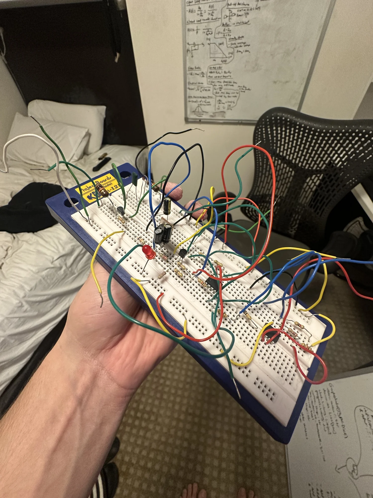
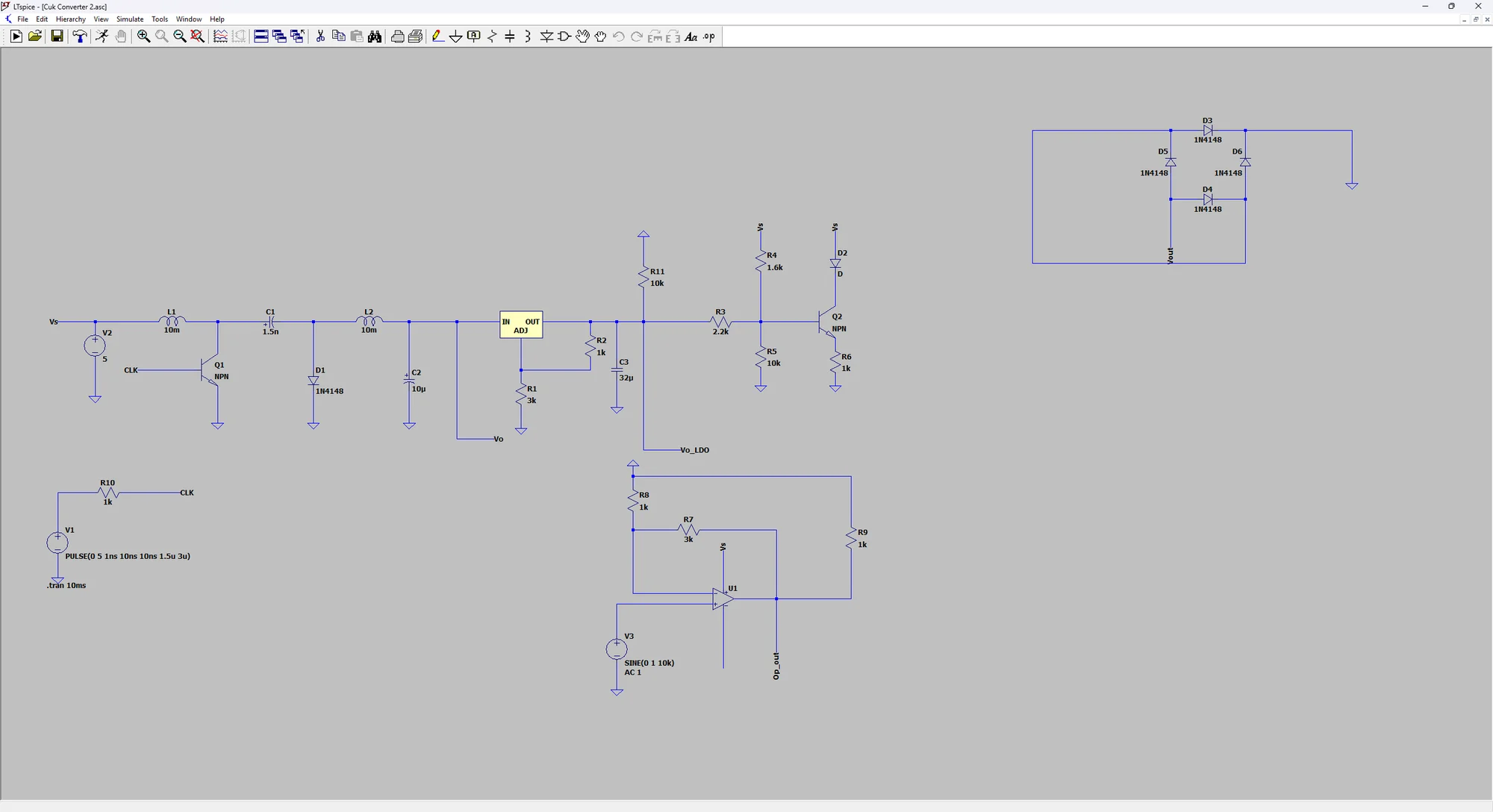
A separate team project used a Ćuk converter to derive a negative supply from a positive 5 V input. The initial converter's output varied with load, so the design added an LM337 regulator and decoupling.
Check Regulation Under Load
The report measured approximately −5.45 V ±0.05 V across the tested 1–10 kΩ loads. An additional warning circuit indicated loss of regulation, and an LM741 amplifier provided a functional load test. This connected switching behaviour, output ripple and regulation to the needs of the circuit being powered.
Connect The Supply To Its Load
An LM741 amplifier provided a functional test of the supply. The exercise brought switching behaviour, ripple and regulator headroom into the same investigation, rather than treating the unloaded output voltage as the only result.
The Engineering Journey
Convert
Use the Ćuk stage to obtain a negative rail from +5 V.
Regulate
Add LM337 regulation, decoupling and a dropout indication.
Load
Check the output with resistive loads and an amplifier circuit.
What This Experience Achieved
The result
Approximately −5.45 V ±0.05 V across the tested 1–10 kΩ loads, as reported for the laboratory prototype.
A Closer Look