Electronics Design & Build
Current-Measurement Device
Convert a load current into a proportional voltage while keeping the sensing voltage drop small.
Experience In Practice
Skills Applied
Technical Skills
Soft Skills
Turn Load Current Into A Voltage
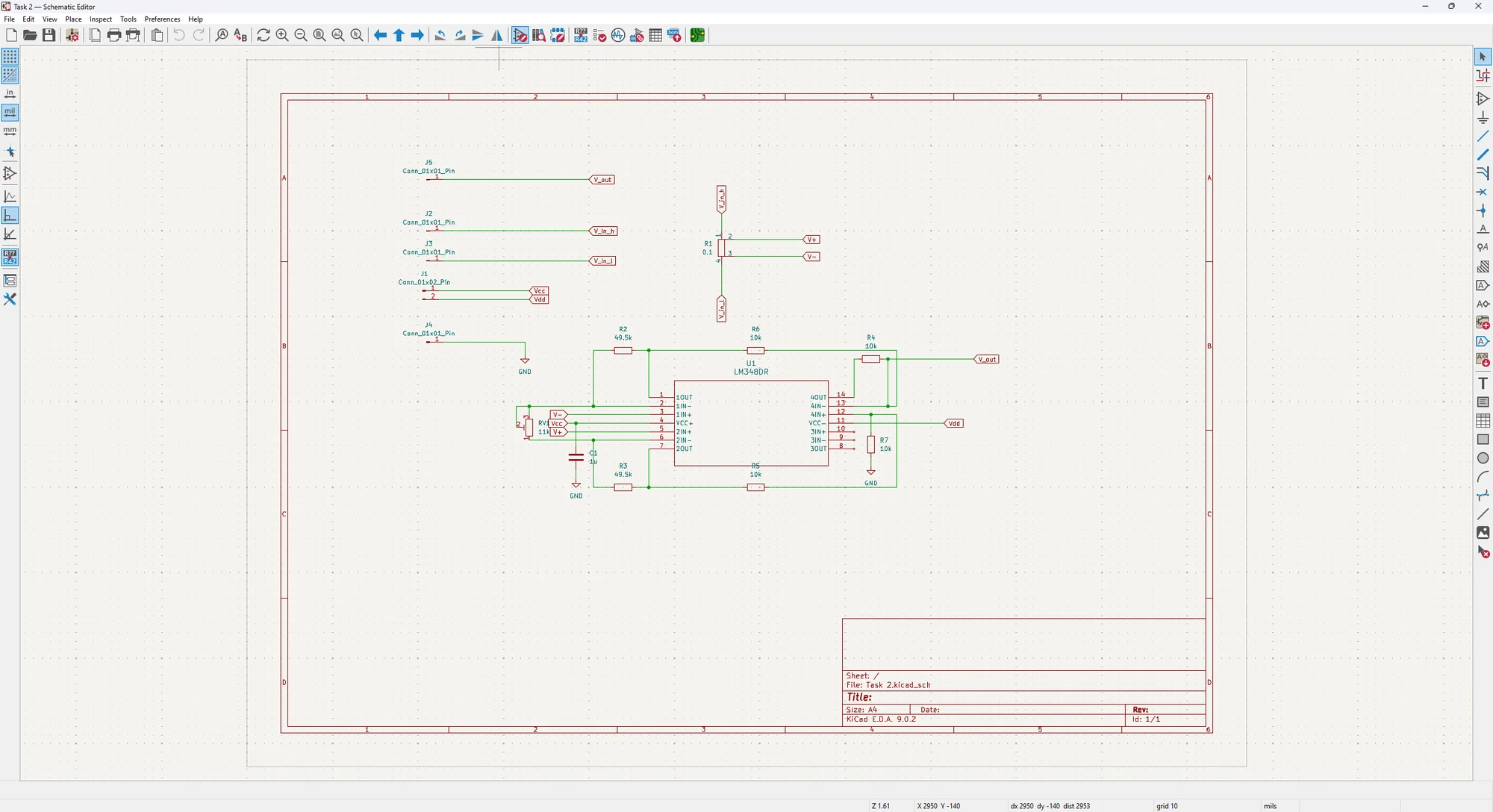
The circuit sits in series with a load. Current through a small shunt resistor creates a voltage drop proportional to that current; the amplifier then turns the small differential voltage into an output that can be viewed as a waveform.
The design supports sensing before or after the load, so the amplifier needs to extract the voltage difference across the shunt rather than simply measure one terminal against ground. This is the connection between high-side/low-side sensing and common-mode rejection.
Adjust Sensitivity To The Measurement
The nominal conversion gain is adjustable from 10 to 100 V/A. For example, 100 mA at 100 V/A corresponds to a 10 V output. Selecting a larger gain makes smaller currents easier to observe, while the ±12 V supply and amplifier output swing limit the usable current range at that setting.
The operating envelope called for current waveforms up to 1 A peak-to-peak and a response within ±3 dB of the selected gain from 100 Hz to 10 kHz. These are the circuit’s design targets, rather than a new claim of calibrated measurement accuracy.
Keep The Sensor From Changing The Load
A measurement circuit should disturb the circuit being measured as little as possible. The design limits the shunt drop to 100 mV, with input impedance no greater than 10 Ω and output impedance no greater than 1 kΩ.
The bill of materials includes a 0.1 Ω shunt. Its small resistance reduces burden voltage, but it also produces a small signal that must be amplified carefully. Shunt dissipation, resistor matching, amplifier noise and thermal drift all affect the balance between useful sensitivity and a stable reading.
Connect The Build To The Board Design
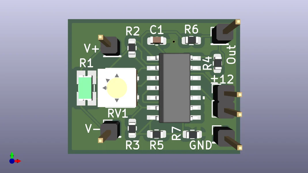
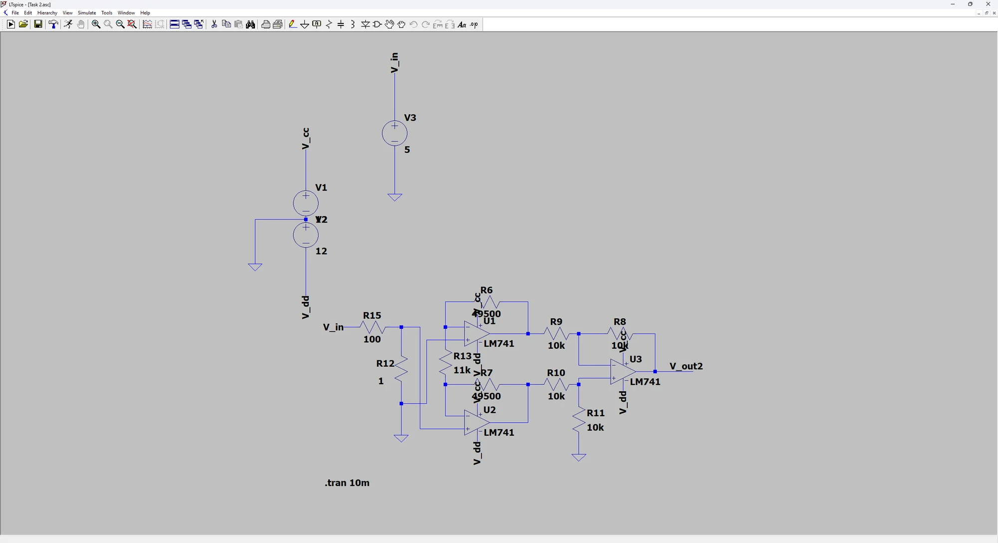
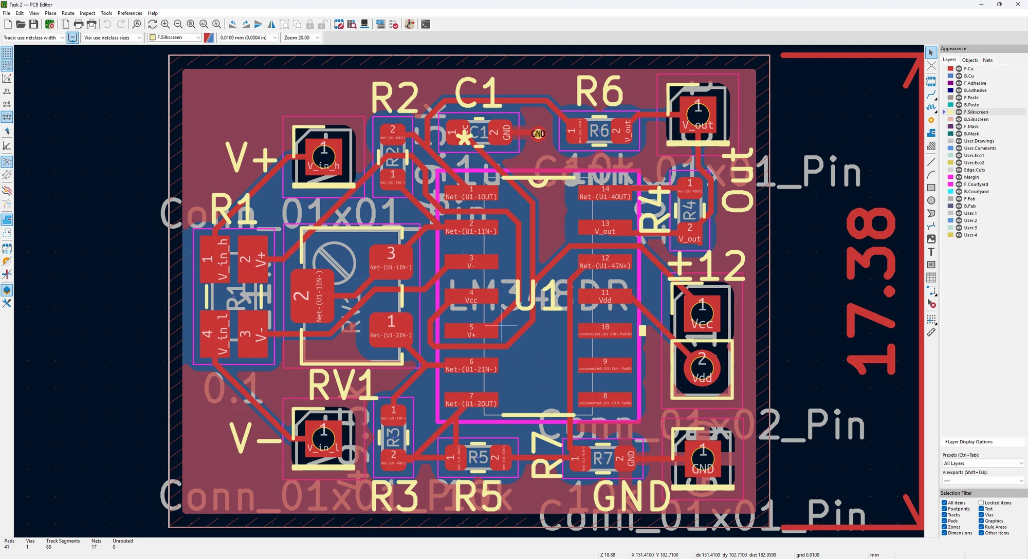
I built the complete current-sensing circuit and developed its LTspice drawing, schematic, PCB routing and 3D model. The component list specifies the LM348, shunt, gain-setting resistors, potentiometer and capacitor, tying the functional circuit to the parts required for assembly.
The Engineering Journey
Sense
Use a low-value series shunt to create a voltage proportional to load current.
Condition
Amplify the differential signal with adjustable current-to-voltage sensitivity.
Build
Complete the circuit and document the PCB implementation and component list.
What This Experience Achieved
The result
A physically built adjustable current-sensing circuit, with simulation, PCB views and a bill of materials documenting its implementation.
From Circuit Design To Parts Selection
Bill Of Materials
The component list turns the circuit and PCB design into specified parts, footprints and quantities for sourcing and assembly. It documents the parts needed to build the design.
| Part / Value | PCB Footprint | Quantity |
|---|---|---|
| LM348 | | 1 |
| 49.5k | Resistor_SMD:R_0603_1608Metric | 2 |
| 10k | Resistor_SMD:R_0603_1608Metric | 4 |
| 1u | Capacitor_SMD:C_0603_1608Metric | 1 |
| 0.1 | Resistor_SMD:R_Shunt_Ohmite_LVK12 | 1 |
| 11k | Potentiometer_SMD:Potentiometer_Bourns_3214W | 1 |
Board Requirements
- Board area
- 384.098
- No of layers
- 2
- No of vias
- 1
- Avg track length
- 7
- Longest track length
- 19.34
Values are transcribed from the design workbook. Dimensional units are not specified in the source.
Download BOM (Excel) ↓A Closer Look
Technical decisions & tools
Conversion gain is expressed in V/A; it is distinct from the dimensionless voltage gain applied to the shunt signal.
Supply headroom limits the maximum output: the highest gain setting cannot represent every current in the nominal input envelope without saturation.