University project
Digital Health Monitoring System
Turning a monitoring specification into testable logic blocks.
Experience In Practice
Skills Applied
Technical Skills
Soft Skills
Translate Rules Into Circuit Behaviour
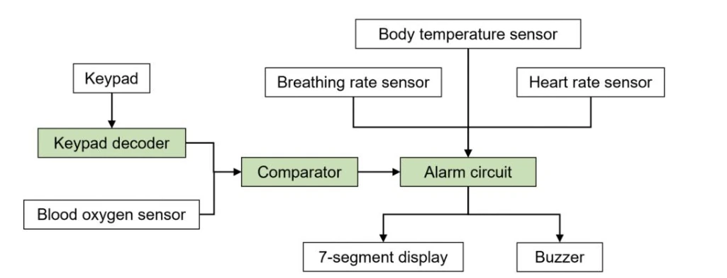
The coursework scenario asked for digital circuitry that combined oxygen, breathing, heart-rate and temperature inputs into monitoring states. The design scope was the logic, rather than a deployed clinical device.
I divided the problem into three blocks so that each could be formulated and checked independently: decode a keypad setpoint, compare the oxygen input with that setpoint, then combine the result with the other inputs.
Resolve The Edge Cases Explicitly
The keypad decoder mapped row and column signals into a BCD digit. The zero key needed explicit handling because the other digit expressions did not naturally update the output for that combination.
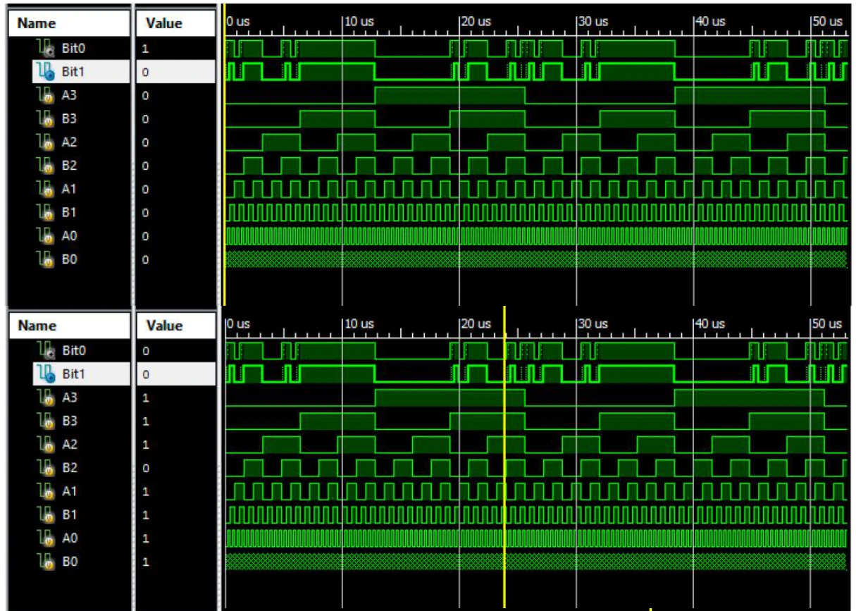
The comparator used the significance of each bit to distinguish above, equal and below the setpoint. Those conditions were encoded into two output bits for the alarm stage.
Use Simulation To Inspect The Transitions
Verilog test code drove the circuits through input cases while ISim waveforms exposed the outputs. The report retained keypad tests and comparator examples, connecting Boolean expressions to observed simulation behaviour.
The alarm logic then combined the comparator result with the other encoded sensor states to produce health, observation and alarm outputs. This case study focuses on the documented logic and simulation work.
The Engineering Journey
Partition
Separate decoding, comparison and alarm decisions into small blocks.
Derive
Write truth tables and Boolean expressions, including special input cases.
Verify
Drive the logic with Verilog test inputs and inspect simulation waveforms.
What This Experience Achieved
The result
A modular digital-logic design with documented Boolean derivation, circuit implementation and simulation evidence.
A Closer Look
Technical decisions & tools
The circuit work links truth tables, gate-level implementation and Verilog-driven ISim checks. This modular approach lets each logic block be understood and verified before it is combined with the next.