Electronics Design & Build
Voltage-Controlled Oscillator
Translate a control voltage into the repetition rate of an analog oscillator.
Experience In Practice
Skills Applied
Technical Skills
Soft Skills
Set Frequency With A Voltage
The oscillator generates a periodic waveform whose frequency changes with an input control voltage. The nominal tuning endpoints are 1 V → 1 kHz and 4 V → 10 kHz, with increasing control voltage producing increasing frequency.
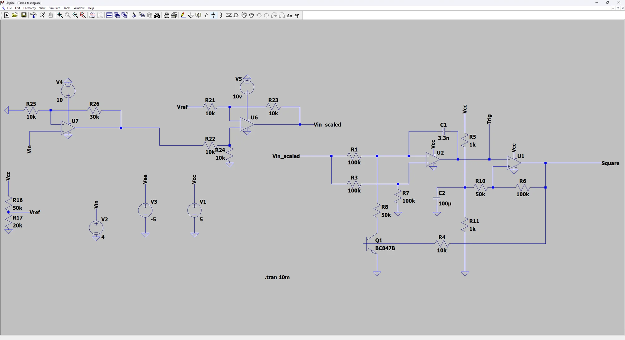
A linear mapping between those endpoints would be f = 3 kHz/V × Vcontrol − 2 kHz over the specified 1–4 V control range. The input-scaling and reference network prepares the control voltage for the oscillator loop.
Connect Integration And Switching
The capacitive-feedback integrator creates a ramp. A comparator monitors that ramp and switches the feedback state, causing the process to repeat. The schematic exposes both the internal triangular waveform and the square-wave output.
Changing the effective drive into the integrator changes the ramp slope. That changes how quickly the switching threshold is reached, and therefore the time between output transitions. The capacitor, resistors, thresholds and control scaling work together to set the tuning behaviour.
Make The Oscillator Useful To Another Circuit
The design targets a 0–5 V output, at least 10 kΩ input impedance and no more than 1 kΩ output impedance. The control input should avoid loading its source, while the output should remain suitable for the circuit it drives.
Monotonic tuning, a near-linear voltage-to-frequency relationship and steady-state frequency stability are the important design goals. Component tolerances, threshold drift and amplifier behaviour influence how closely a physical oscillator follows the ideal mapping.
Complete The Physical Circuit
I built the complete oscillator and used the LTspice schematic to document its input scaling, integration and switching stages. The stated tuning endpoints describe the design specification; no measured tuning curve or distortion figure is added beyond the supplied evidence.
The Engineering Journey
Scale
Prepare the input relative to the reference level.
Integrate
Connect the control signal to the ramp-generating stage.
Switch
Use the comparator and feedback path to form the oscillator loop.
What This Experience Achieved
The result
A physically built voltage-controlled oscillator, documented through its LTspice topology and the connection between the control input, ramp generation and square-wave output.
Technical decisions & tools
The ideal 3 kHz/V slope follows from the 1 kHz and 10 kHz endpoints separated by 3 V. It applies to the nominal 1–4 V control range.
The triangular ramp is an internal oscillator state; the schematic also provides a switched square-wave output.