Sequential Logic Design
Vivid Light Show Controller
Two state machines turn button presses into a four-colour sequence and a timed musical cue.







Experience In Practice
Skills Applied
Technical Skills
Soft Skills
Define What Each Button Should Do
The concept is an interactive light display with four colours: Magenta, Cyan, Yellow and White. Forward advances one colour, while Skip advances two. After three Forward actions without a Skip, the controller requests a musical beep for one clock cycle.
The outputs are a two-bit colour code and a one-bit music signal. Reset returns the colour to Magenta and clears the musical-cue progress. With neither button pressed, the state holds; the design also treats both buttons pressed together as a hold.
The challenge is remembering two different things: the current colour and progress towards the musical cue. A colour alone cannot identify whether the preceding actions were Forward or Skip.
| Input | Colour Action | Music Progress |
|---|---|---|
| Reset | Return to Magenta | Clear to zero |
| F=0, S=0 | Hold | Hold; no cue |
| F=0, S=1 | Advance two colours | Clear to zero; no cue |
| F=1, S=0 | Advance one colour | Advance count; cue on the third Forward |
| F=1, S=1 | Hold | Hold; no cue |
F = Forward and S = Skip. Button actions are evaluated by the clocked logic.
Separate Colour State From Sequence Memory
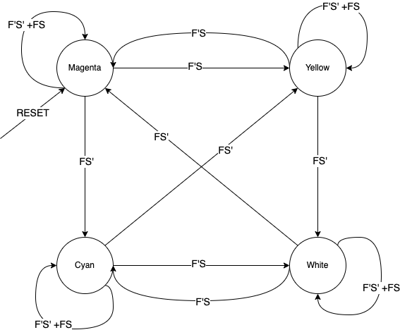
I split the design into a colour state machine and a music state machine. The colour machine needs four states, encoded as Magenta=00, Cyan=01, Yellow=10 and White=11. Its state directly identifies the displayed colour.
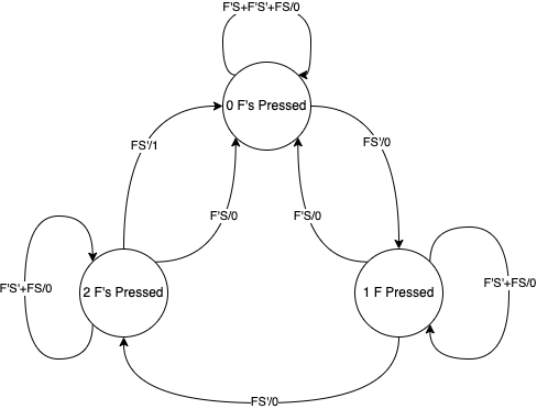
The music machine needs three states: zero, one or two accepted Forward actions since the last Skip or musical cue. A Forward from the two-action state requests the cue and returns the counter to zero.
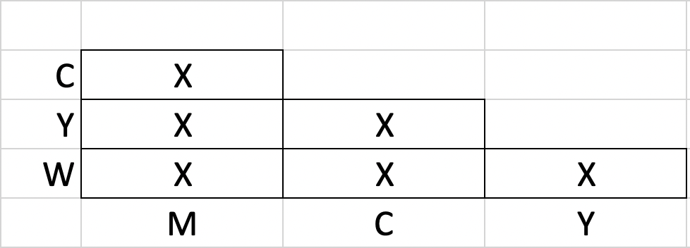
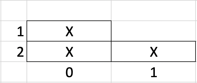
I checked whether any states could be merged. Different colour states already have different outputs. The music states also remain distinct because the same future Forward sequence reaches the cue at different times. Two state bits per machine are sufficient.
Make Every State Transition Explicit
The colour table below contains all 16 combinations of current colour and button inputs. Reading across a row shows hold, skip, forward and hold again. In binary, Forward adds one modulo four and Skip adds two modulo four.
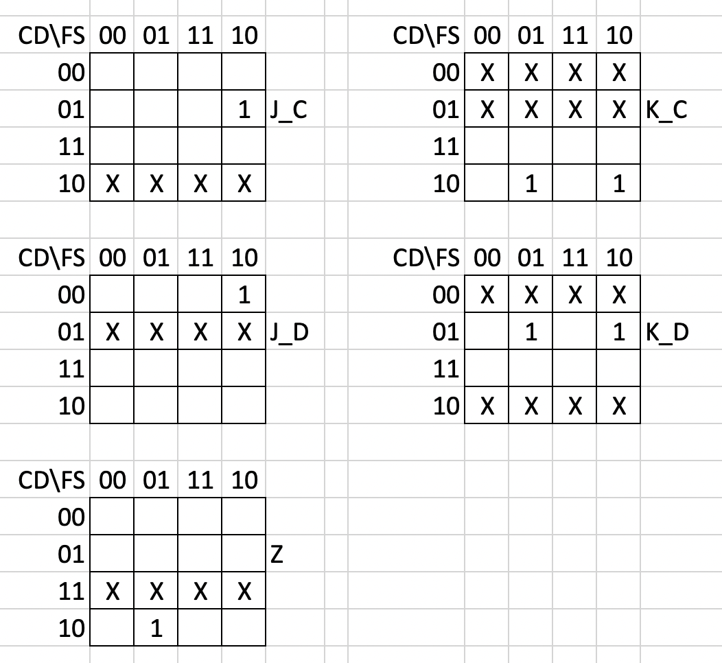
The music table contains all 12 valid state/input combinations. Pauses preserve progress; Skip clears it. The unused music encoding 11 is excluded from the three-state design and was available as a don’t-care when minimising the logic.
| Present Colour · AB | FS=00 · Hold | FS=01 · Skip | FS=10 · Forward | FS=11 · Hold |
|---|---|---|---|---|
| Magenta · 00 | Magenta · 00 | Yellow · 10 | Cyan · 01 | Magenta · 00 |
| Cyan · 01 | Cyan · 01 | White · 11 | Yellow · 10 | Cyan · 01 |
| Yellow · 10 | Yellow · 10 | Magenta · 00 | White · 11 | Yellow · 10 |
| White · 11 | White · 11 | Cyan · 01 | Magenta · 00 | White · 11 |
Each cell gives the next colour and its two-bit output. Reset selects Magenta · 00.
| Present Count · CD | FS=00 | FS=01 | FS=10 | FS=11 |
|---|---|---|---|---|
| 0 · 00 | 0 / 0 | 0 / 0 | 1 / 0 | 0 / 0 |
| 1 · 01 | 1 / 0 | 0 / 0 | 2 / 0 | 1 / 0 |
| 2 · 10 | 2 / 0 | 0 / 0 | 0 / 1 | 2 / 0 |
Each cell is “next count / music output”. Reset selects count 0 · 00; the cue occurs on the third Forward action.
Reduce The Table To A Small Set Of Rules
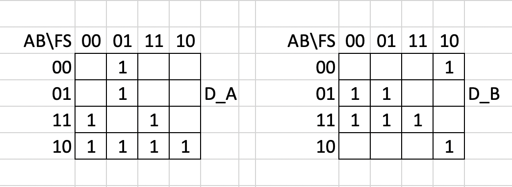
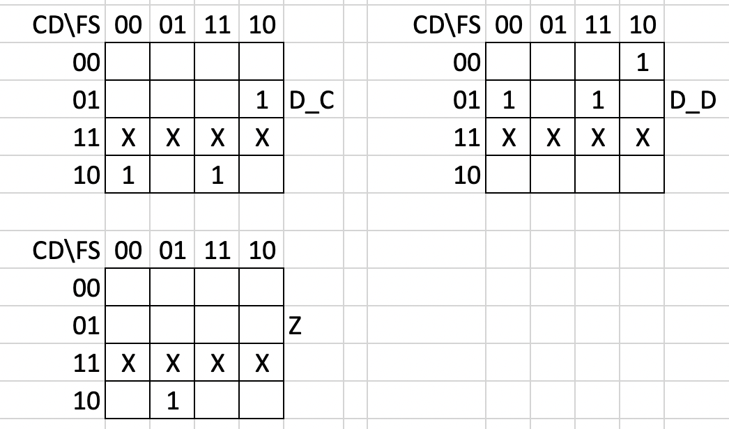
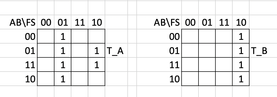
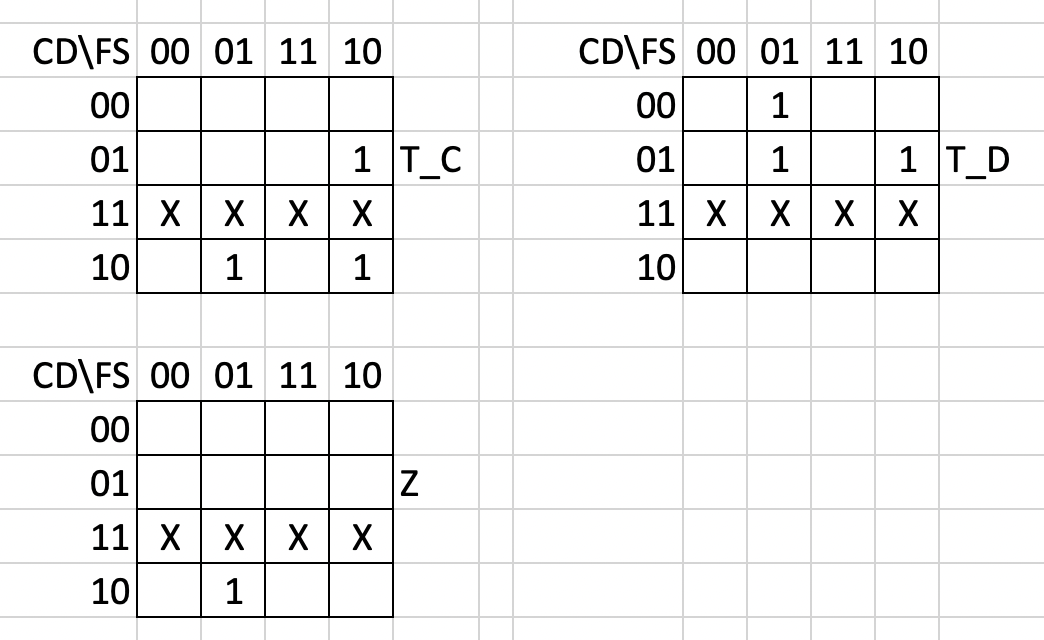
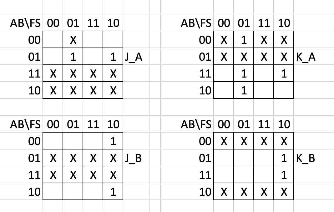
I used state assignments and Karnaugh maps to derive the flip-flop excitation inputs. A useful way to understand the colour logic is to look at which state bits toggle.
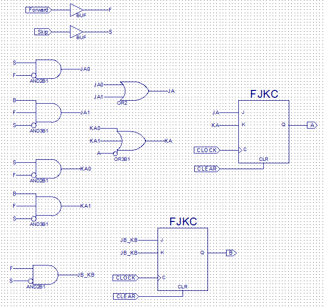
The least significant colour bit B toggles only on Forward. The most significant bit A toggles on Skip, or on Forward when B is already 1 and the increment carries into A. Neither bit toggles for input 00 or 11.
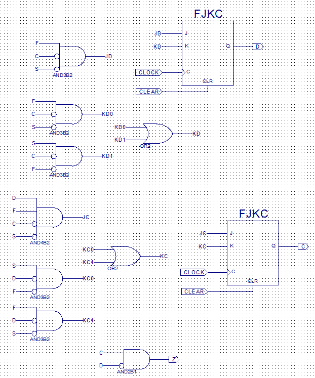
The equations below restate those transitions directly from the state tables. For the music machine, count 2 is encoded CD=10, so the cue requires that state together with Forward alone.
TB = F·¬S
TA = ¬F·S + B·F·¬S
Bnext = B XOR TB
Anext = A XOR TA
MUSIC = C·¬D·F·¬S
A and C are the most significant state bits. · means AND, + means OR, ¬ means NOT; TA and TB are colour toggle requests.
Implement The Same Behaviour With D, T And JK Flip-Flops
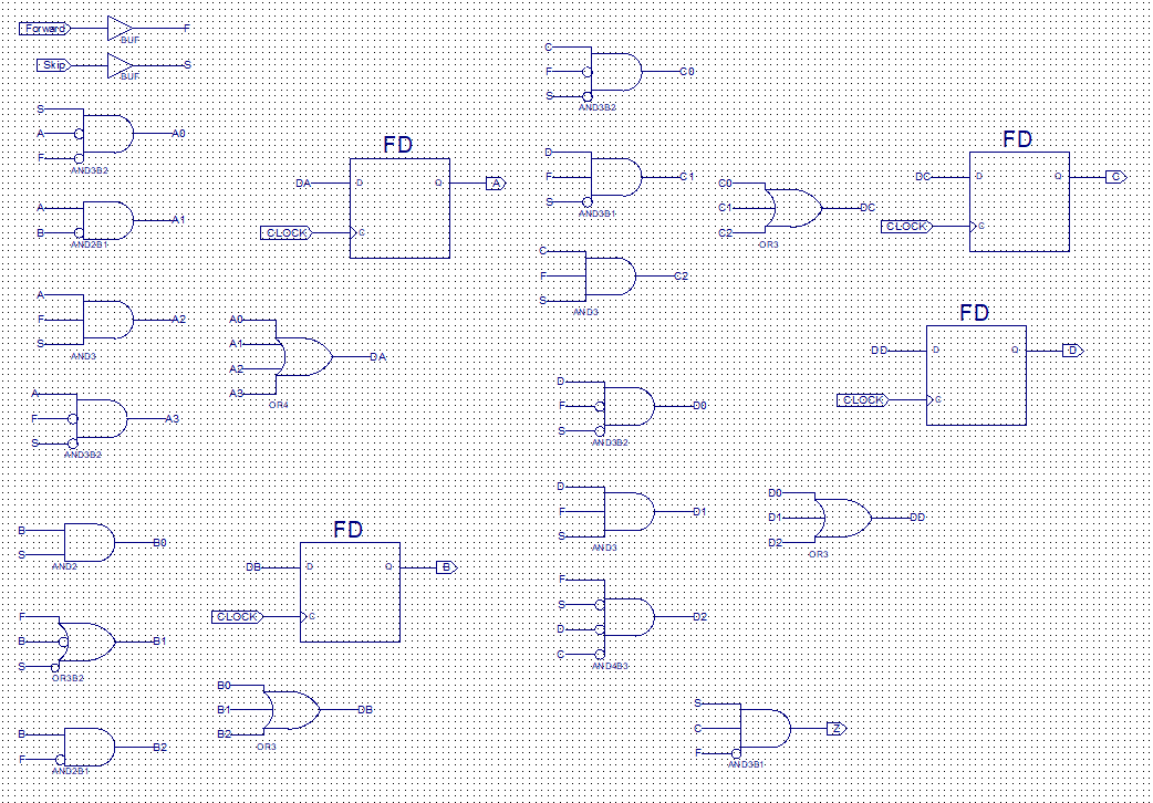
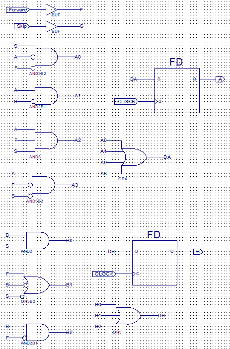
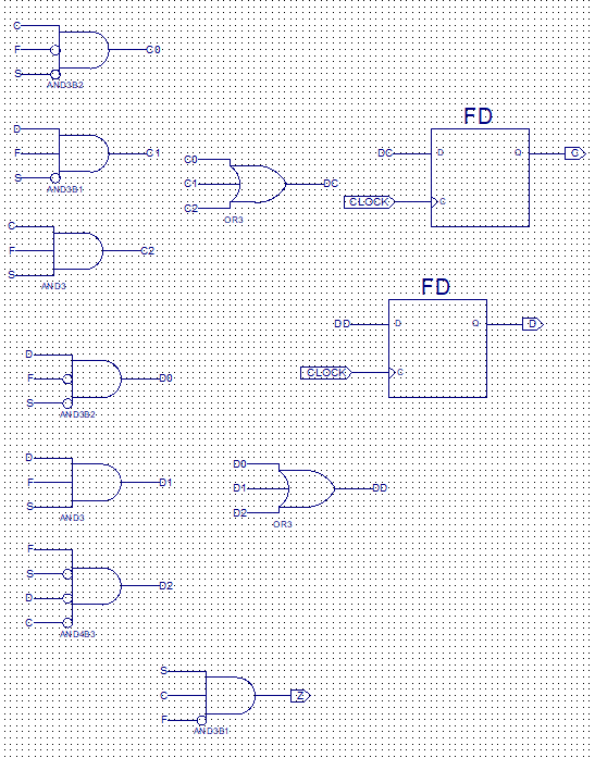
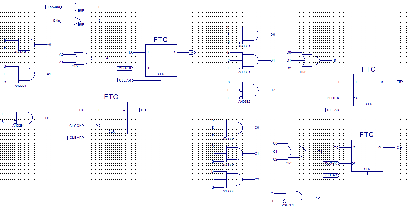
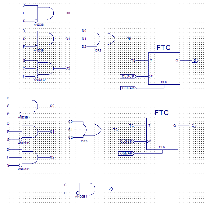
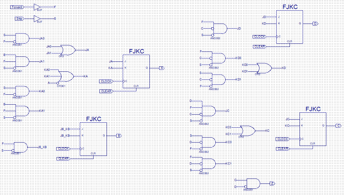
I developed three gate-level versions around the same state-transition requirements. D flip-flops take the required next-state bit directly. T flip-flops need a toggle request when the bit must change. JK flip-flops use excitation conditions that set, clear or retain each state bit.
For each version, I derived the excitation table, grouped the corresponding Karnaugh maps and drew the colour and music circuits. The slideshow includes the complete D, T and JK schematics as well as the separate logic blocks.
The excitation table explains why the Boolean networks differ even though the intended controller behaviour is the same. X is a don’t-care: either value produces the required transition when the other input is fixed.
| Q → Qnext | D | T | J | K |
|---|---|---|---|---|
| 0 → 0 | 0 | 0 | 0 | X |
| 0 → 1 | 1 | 1 | 1 | X |
| 1 → 0 | 0 | 1 | X | 1 |
| 1 → 1 | 1 | 0 | X | 0 |
Follow The Sequence In Simulation
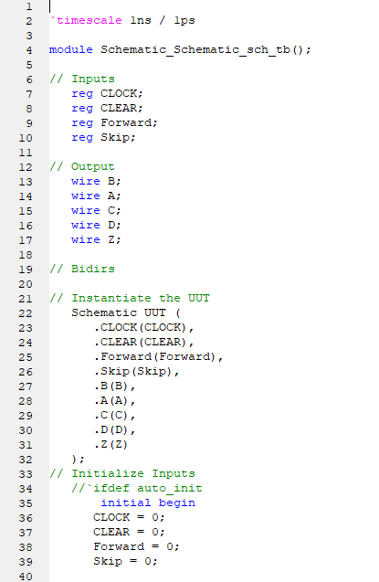
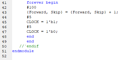
I connected the controller designs to Verilog test inputs and used ISim to inspect button signals, colour bits, music-state bits and the cue output. The retained stimulus code cycles the Forward/Skip input pair and pulses the clock; six waveform captures are included in the slideshow.
A simple trace makes the intended behaviour easy to follow: reset to Magenta, then three Forward actions reach Cyan, Yellow and White, with the cue on the third action. A Skip anywhere in the sequence clears progress towards the next cue.
This trace is derived from the design’s state tables; the original simulation captures are shown separately so the intended transitions and the recorded circuit behaviour can both be inspected.
| Action | Colour After Action | Forward Count | Music Cue |
|---|---|---|---|
| Reset | Magenta · 00 | 0 | 0 |
| Forward | Cyan · 01 | 1 | 0 |
| Forward | Yellow · 10 | 2 | 0 |
| Forward | White · 11 | 0 | 1 |
| Forward | Magenta · 00 | 1 | 0 |
| Skip | Yellow · 10 | 0 | 0 |
| Forward | White · 11 | 1 | 0 |
The Engineering Journey
Model
Separate visible colour from the memory needed to recognise three Forward actions.
Minimise
Assign states and use truth tables and Karnaugh maps to derive excitation logic.
Implement
Build D, T and JK versions and inspect their signals in ISim.
What This Experience Achieved
The result
A complete sequential-logic design record: two state machines, explicit transition tables, Karnaugh-map derivations, three flip-flop circuit implementations and simulation captures.
Technical decisions & tools
The colour machine has four states and the music machine three. Their separate two-bit registers make the two responsibilities explicit.
Music is a Mealy-style output: the current music state and Forward/Skip inputs determine the cue. The state-table explanation assumes a button action is sampled for one clock interval.
The unused music state 11 is a minimisation don’t-care, not a fourth progress state. Reset establishes the intended starting state.
The readable equations on this page are derived from the transition tables; the image gallery retains the original design diagrams and Karnaugh-map working.